Friday, December 4, 2015

Color Is Everything

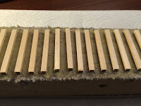
Finally got around to trying different approaches for coloring the ties.  I was going to post this almost two weeks ago when the painting was done, but decided that for a proper evaluation I also needed the contrast of the ballast.

The first three pictures are the ones I felt gave the best results:
First, Rustall #2 solution as suggested by Mike Cougill in his book,  Detailing Track
Second and third are a random combinations of Umber and Gray PanPastels plus a drop or two of India Ink turned into a wash with 91% ISO.  The darker ones are heaver on the gray PanPastel or India Ink and represent more recently replaced ties


For full disclosure, here are a few other options I tried:
First up is a spray paint approach using a Testor's Graphite Dust -- It ends up being too metallic looking
Next are some paint-pen trials, but despite being labeled brown, have far too much red in them

I think I'll stick with using the Rustall #2 as a base and then come in with some of the washes and randomly distribute a few darker ones to show some age variation.

I am pleased that the wood-grain distressing shows up nicely with this weathering method.

The ballast is an approximate 2/3, 1/6, 1/6 mix of medium, fine, and coarse sizes of Woodland Scenics Light Gray ballast.  Prototype photos below show varying sizes of rock, so I think mixing them while favoring the medium size provides that look.  If anything, I probably should up the contribution of the "fine" size.  In the future I might try some real rock products from, say, Arizona Rock and Mineral.


Look for a post later in December, hopefully with tie plates (from Jim Lincoln and Monster Model Works), rail and joint bars (still need to order those from Bill Brillinger's Precision Design Company!

Monday, November 2, 2015

Ties

The test track build continues.   This installment is a short one; just a couple pictures of the ties glued down.
I used standard yellow wood glue to attach the ties to the homasote.  Two ties were initially out of alignment and replaced, so that provided a nice contrast that highlights the distressing.

The ties were distressed first by dragging a fine-tooth hooby saw perpendicular to the ties to create a grain, further sliced up with the sharp end of a tiny screwdriver and finished with a hopefully random distribution of knife slices along the tie edges to smooth any perfectly square corners.

I first read about these distressing techniques in Mike Cougill's publication Detailing Track.  Also see Vol 7 of The Missing Conversation for additional discussions on track.   I also observed Trevor Marsall use similar techniques in his Roadshow series on Trainmasters.tv (paid site, but worth it).


Next up is staining and coloring followed by ballast.   Per Lance Mindheim, I'll look into the products offered by Arizona Rock & Mineral.

I also have the rail ready to go...Trying something new for this handlaying adventure: prototypical 39' sections of rail.  I understand that I could go the "easy route" and lay three-foot sections of rail and glue on joint bars every 39ft, but I'm trying to recreate that distinctive wiggle in industrial track that the individual pieces might provide.  We shall see.

Thursday, October 29, 2015

Homasote Splines

I constructed the base for the test track out of Homasote Splines this evening.  The finished product seems like it will work well, but there were some rough spots getting here.

 First, while those knife-edge blades leave a very nice edge and generate a fraction of the dust that anything with teeth would, they seemed prone to wobble, especially as they warmed up.  This meant I constantly needed to make fine adjustments to the jigsaw attack angle and was prevented from using a guide like I had hoped.  The result is some slightly wavy cuts.

This makes for a tedious process with lots of long slow cuts, so I tried doubling and quadrupling the material.  Anything more than two and the blade would wander too far on the bottom piece and leave you with nothing but scrap.


Alas I got eight good two-foot long pieces that overlapped to form a three-foot long section.  I used a standard wood block plane to smooth down the top (track) surface and screwed on a left over piece to the bottom side to make up for the variations in piece height.  This is only necessary since this test section lives at the workbench.  Normally, the pieces will (should!) get cut closer to desired size and the bottom just screws onto the risers or other benchwork supports.


So, it might be that future spline production is done from full sheets on a table saw outside.  In mid-November, I'll be visiting a model railroad that uses this track support technique, so construction details will likely be some of my questions.


In other news...I ordered a full set of the tie rack jigs from Fast Tracks -- one of each spacing (20", 22", and 24").  My research trip did yield that the tie spacing was 20" -- at least on the remaining track where one could actually see the ties.  This was close to a turnout, so I didn't take it as gospel that the whole line used this standard.  Some variation, especially between more and less frequently used tracks will provide some visual appeal as well.

For this test track though, I doubt I'll wait until the jigs arrive.  Shouldn't be too hard to lay 3 feet of ties by hand.

Looking ahead to track laying, I'll close with some prototype photos.  It should be fun replicating track in this condition (and having it still operable)...


Tuesday, October 20, 2015

Quick Update

I usually try to keep the project-related postings coming about once a month and in order to keep that frequency, here's a quick post about current plans.  The GBW 7080 project was moving along nicely, culminating in getting couplers mounted on it when I realized that in order to make any more progress, I'd have to have a test track in order to confirm coupler heights and finish work on the trucks. Since P:48 is new for me, many projects pause while waiting for the next internet order of supplies and tools and funds from the sale of unused HO scale equipment.

The plan is to create a two-foot test section of track both to try out some of the construction and detailing aspects and result in a functional test track.  I"ll build this on homasote splines.  To that end, supplies have been rolling in to get that test track going:
While at Red Cliffs, I also ordered the parts to make a #8 turnout as well.  The corresponding kit from American Switch & Signal turnout castings are lined up for the next Protocraft order to compare.

Also, I have one more opportunity to visit the prototype here in the next week, albeit probably only briefly.
Chief research items are:
  1. Length of switch points in the three remaining turnouts, including the one to the mainline if I can safely measure it.
  2. Spacing between the cross ties.  This is branch line trackage and I'm trying to decide which -- if any -- of the Fast Tracks tie jigs can help me or if I should just roll my own.
  3. Number of holes in the tie plates.   I'm assuming four-hole, as this was light density trackage.
Stay tuned for construction progress and photos.


Oh, and fun fact, this is post #50 since the beginning on 27 April 2013 (907 elapsed days [~2.5 years] and an average of one post every 18 days).

Saturday, September 12, 2015

GBW 7080 - Part #3

This and successive postings of this title will follow the project to convert this 2-rail Atlas Trainman model of a ACF 50' boxcar lettered for the Green Bay & Western into a Proto:48 model.  See Part #1 and Part #2.

Couplers
With this installment, we continue with the change out of the couplers.  Fortunately, the grotesquely oversized Atlas coupler boxes are merely screwed on, making for easy removal.  After drilling and tapping new holes that line up the new Protocraft coupler boxes, they too mounted on with screws.

Just for comparison, here are the original (Atlas) and new (Protocraft) couplers side-by-side:

I decided to go with the Protocraft couplers on this build after the frustrations of trying to reliably assemble the San Juan couplers.  Their brass construction and reliable bottom-operating uncoupling mechanism were the main motivations and the fact that they come assembled sealed the deal for now.

Getting the couplers installed back on the underframe was painstakingly slow as I realized all of the tools I needed for this level of work and I didn't own.  Thankfully, "the internet" delivers relatively quickly.  :-)

A few shots follow to show the completed installation of the Protocraft couplers and wheels with narrowed bolsters from Lincoln P48 Engineering.  

I still have some work to do regarding the trucks.  The Protocraft wheels don't have the shaft length on them to still use the rotating roller bearings -- I need to try Jim Lincoln's replacements here.  There are some options here, but for now, at least it is back on the trucks.  Now I just need to build a test track so I can verify that the couplers are at the correct height.

Body Modifications
I've started on prep work for upping the detail on the body.  The plastic stirrups were clipped off in anticipation of building out the sill plate to the end and mounting new brass ones.  As mentioned before, part of the extra reinforced needs to be trimmed back to only be under the door.  Also begun was the process of removing the molded on ladders -- this will be a slow process and sure to result in the need for some repainting work.  Matching GBW yellow will make for an interesting project as well.

Saturday, August 22, 2015

On The Ground Again

I had the opportunity to visit the Fairgrounds Branch again in mid-August 2015 and it was a good thing I did.
The former Safeway Bakery building was in the process of being covered with insulating panels meaning the exterior photos I recently captured will be the last ones anyone can get.
Prior to obtaining these photos, I had been thinking about the kinds of traffic and the car types that would've served this industry.  It isn't big enough to ship anything out, so rail service would've been limited to inbound raw materials.  That could include flour and sugar plus other commodities like boxes and such.  Pneumatic cars seemed out of the question until I spotted the small set of doors to the left of the rollup door and dock (upper right photo above).  This would've been a perfect place to store a hose and make connections to indoor piping.  The same could be said for the two side-by-side former doors in the upper left photo.  Also noticed was the supports for an awning that hung over the dock.

The other remaining item that had been holding me back from building track was the turnout details.  American Switch & Signal makes great turnout kits for Proto:48 (link is to the Protocraft distribution of said parts) but I needed to know for sure which type of frog would've been in use.  I had assumed that the answer would be simple bolted frogs and the following detail photos confirm this:
I also walked this turnout again in the daytime to confirm that it had a frog angle of #8.  One farther down the track that started the spur into Schutte Lumber measured out to be a #7.  I"m realizing now that I forgot to walk off the distance of the switch points; all of the kits I've seen have 16' 6" points.

I'm impressed by this particular switch that almost has a diverging route on the normal alignment.  It is those types of track variances that I hope to recreate (and have the equipment actually operate...).

I also captured a few more shots of the switch throw mechanism in order to be able to compare to some the products available out there:
I'll be in Kansas City again in October 2015, but may not have an opportunity to get to "The Hill" as the primary purpose of the trip is a wedding.

Tuesday, August 11, 2015

GBW 7080 - Part #2

This and successive postings of this title will follow the project to convert this 2-rail Atlas Trainman model of a ACF 50' boxcar lettered for the Green Bay & Western into a Proto:48 model.  See Part #1.

The first two items up for change are the couplers and trucks.  Choices for the couplers mentioned in the first post included Type 'E' models in delrin from San Juan Car Company or in brass from Protocraft.  The trucks are easy to modify (narrow) with drop-in bolster replacements designed by Jim Lincoln and produced by Shapeways.

Couplers:
I ordered one of each type of coupler kit offered by San Juan, with the difference being the "scale shank" versus one that fits in a Kadee coupler box.


Unfortunately, that means it doesn't fit an Atlas coupler box.   Plus, they are difficult to assemble to a reliably operating state.  Of the two-and-a-half I've put together so far, the first was a dud because what looked lie flash was mistakenly trimmed off and this rendered the coupler unlockable.  After replacing this part, it now one works OK and holds under a moderate load against another coupler, but the other one doesn't remain locked either (for a different reason).

The "scale shank" ones yielded slightly better results.   Out of the package, they looked more cleanly molded and sharper.  Maybe because I knew more about what to do, they went together more smoothly, but some of the same operating reliability challenges were still there.   Perhaps after a dozen pair of these I could get the hang of it.

The couplers from Protocraft come assembled and work right out of the box.  There are few subtle differences between these and the SJCC version, with the Protocraft ones looking just a bit bigger.   They come with the bottom lift pin mechanism already in place.   I'll post more updates when I get these mounted on a freight car and hopefully operating with the lift bar.

Here's a rather poor comparison photo of all four couplers. From left to right, you have Atlas Original, SJCC "standard", SJCC scale, and Protocraft.

In summary, with the Protocraft couplers starting out reliable and coming with coupler boxes, I'm leaning in that direction for general usage.   They are about three times the price though.

Trucks:
The first 3D-printed parts arrived that I ordered arrived and the use of the "black strong-and-flexible" material seems to be a good choice.  They cut away from the sprues cleanly and the finish somewhat resembles what a rusty metal underframe would look like.  Of course, one does not see much of the bolster itself in a model siting on the tracks, so the point is: they don't distract.

However, I'm again waiting on more parts from Shapeways, as the first two I ordered were for the newer style Atlas trucks, whereas the model I have has the older style trucks.  According to Mr. Lincoln, the difference is the width of the sideframe: Newer ones are 1/8" and older ones are closer to 3/16".

I put the Protocraft wheels in one truck anyway just to see what they'd look like and I am impressed.  There's some slop in them but that is due to the sideframe difference noted earlier.

The inability to immediately assemble the trucks with the narrowed bolster prompted me to think about freight car trucks in general.  The Atlas ones are a rigid frame design and based on some Proto:87 experiences of another modeler I read about, it got me thinking that I should probably seek out a fully sprung truck to hopefully better navigate the track.

Now that's mostly forward thinking because I don't actually have any track yet to run this car on and at the rate things are going it'll be a close race between the cart and the horse -- maybe I'll get a test track section built before winter arrives.  Nor do I consider that one source a doomsday scenario -- but P:48 is the same proportions as P:87, so flange depth and tread width are important concerns -- and I want to model rickety industrial track.  I'll have mass on my side though; O scale equipment is easier to weight down.

The conversation on the sprung trucks comes from the 'p48_modeler' Yahoo group.  An interesting read if you have the time and interest.

Future:
The latest Model Railroader magazine contained an article on modeling left over dunnage and generally sprucing up the interior of a box car.   I think I will follow some of those recommendations for this model, since it already comes with movable doors.

Tuesday, August 4, 2015

1:48 Vehicles

I've seen laments around the web that vehicles in 1:48 are hard to find.  So it came as a surprise to me that one source could be my local Menards (a Midwest USA home improvement store).

While browsing their collection of "O Gauge Train Stuff", I found what appears to be a decent representation of a Mack Type R (or one of its variants).  The Mack R-series was produced between 1966 and 2005.  I don't know exactly which year this particular model is patterned after, but at a glance it would appear to be of 1970s of 1980s vintage (mainly since there aren't any rounded corners).

Some of the details look a bit chunky, but it says 1:48 scale on it and, heck, for $6.99 USD, it would probably serve as a starting point or at least a stand in.  Schutte Lumber wold need some delivery trucks.

There's also a delivery van and an ambulance, but they seem to be a bit new for my era.  The van is a later Chevy model and the ambulance is a Ford F350.

Sunday, July 19, 2015

GBW 7080 - Part #1

This and successive postings of this title will follow the project to convert this 2-rail Atlas Trainman model of a ACF 50' boxcar lettered for the Green Bay & Western into a Proto:48 model.


The prototype is a lot (#11-06860) of 150 50' boxcar built in June 1979 by ACF Industries.
(Transcribed ORER data at the previous link is courtesy of the Green Bay & Western Historical Society).

They were used in general service and lacked any special equipment for one of GBW's signature traffic lanes: finished rolled paper.  However, quite a few other products were generated in their service area, so I should have no trouble determining a suitable lading for this car while in service on the Fairgrounds Branch.

I've only been able to find photos of these cars after they'd left GBW ownership; many were transferred to short lines, including these four that went to Hartford & Slocumb:
Serveral other photos of adjacent car series are also available: See this reference photo and the one included below as examples of the ones built by Evans-SIECO.


The 74xx cars were slightly more populous (200 cars in the lot) and are nearly identical, except for the squared off sill plate.

Proto:48 Conversion
Here's where the fun begins.  There are a few discrepancies between the prototype and the model, most notably the side sill.

Side Sill
Atlas' model appears to be a combination between the various GBW car series in what I could only describe as an attempt to please everyone.  The model has a two-step sill that is full height across the door and the adjacent four panels on either side.  It then steps down for one panel's width and runs about half height for one more panel length.  Along the length of the outermost panel, the sill is gone and the stirrups hang directly from the body there.

The stirrups and lack of sill match the 7450-7649 series car by Evans.  The angled transitions in side sill height match none of the 7xxx series cars, though having two different heights is reminiscent of the 7450-7469 series, except that the extra height reinforcement was limited to the space directly under the door.  I've seen examples of the height transition being both vertical and angled.

The cars in the 7400-7450 series that were constructed around the same time by FMC have a longer side sill reinforcement spanning more of the car length, but the sill runs all the way to the end of the car.

It would be nice if the Atlas model at least represented one of the series correctly and then the recovery process would be limited to decals.  Alas, some styrene and paint will be required to fix this up.

Summarizing the options:
To SeriesPositivesNegatives
7000 to 7049Has the two-step side stillWas built by FMC
7050 to 7199


  • Was built by ACF
  • Is lettered correctly (lot #, car #, etc.)
  • Has correct size door
  • Need to build out side still to full length
    Need to add under door reinforcement 
    7200 to 7407Was built by ACF
    7450 to 7649


  • Closest match for sill  at car ends
  • Closest match for stirrups


  • Model has corner posts
  • Was built by Evans/SIECO
  • Latter half of this series was blue

  • The build out of the sill to match the 7050-7199 series car appears to actually be a combination of addition and removal.  The model's current 13" side sill seems appropriate for the reinforced portion under the door (based on some crude scaling in a few prototype photos) and would need to be cut down to approximately nine inches on the rest of the car and then extended at that height to the car ends.

    This seems like the smallest amount of work, so the target car series will be the one the model intended -- by the manufacturer's car numbering, at least -- the 7050 to 7199 series.

    Minor Details
    The only other cosmetic upgrades I can see right away would be wire grabs since in this scale, the shadow behind those should be noticeable.  Plus, I already have to make new stirrups anyway.

    The model has the newer "black-box" style COTS markings, but I'd have to confirm when this started to appear.  Atlas populated theirs with original dates, so it may very well be correct.  Followup: Seems that this is correct.  Tony Thompson's excellent research on the SP resulted in this rule applicability timeline, and two-panel COTS stencils were required on new cars starting in 1974.

    The stenciling has the inside length off (short) by one inch.  ORER data indicates 50'7".

    If I get excited, I'll see if there's an easy way to make a thinner lower door track.  Prototype photos show this being considerably thinner and having a shadow against the car than Atlas' representation.

    Trucks and Couplers
    Based on comparisons to the prototype photos, the trucks themselves look to be correctly size and proportioned.  Atlas' model has rotating end caps on the roller bearings.  Of course, I'll need to narrow the bolsters (planning to use parts from James Lincoln here) and get replacement wheels from Protocraft's selection.  I'll probably also go with the couplers from Protocraft or maybe San Juan Car Company

    Wednesday, June 24, 2015

    O Scale Resource Magazine & Korber Models

    I found myself at Korber Models website today and while browsing their building kit offerings, noticed that they offer a Quonset hut that will be of use when I get around to building Motor Parts Distributors -- it has a double Quonset hut at the top of the property next to Terrace St.

    Some of the detail parts that they offer might also come in handy -- the steel storage tanks and possibly the rooftop water tanks would fit on some of the Fairgrounds Branch buildings.

    I didn't just happen to find this site -- I followed it through an advertiser link in the O Scale Resource online magazine that was just released today.  It's free, so if you are into O scale, you have no reason not to subscribe.  Or, for that matter, since it is free, follow along anyway and learn some techniques or information that will likely apply to your chosen scale.

    Monday, June 22, 2015

    Battenfeld Grease & Oil Company

    Updated 22 June 2015 with a few minor details on the company history and inbound commodities.

    This installment of the Fairgrounds Branch tour examines the Battenfeld Grease & Oil Company, which was spot #327 on the 1972 Map.  Operations began around 1911 and I found this ad from 1924.

    J. R. Battenfeld started the company at 3148 S Roanoke Road, which is actually across the street from the Farigrounds Branch, more on that later.  The company was involved in research into lubricating greases beginning in 1938 through 1940 (the time of the documentation).  At least one of their products was 'Tube-A-Kalk', first manufactured around 1949.  From an article about the owner's house, I learned that they made a lot of grease compounds: "... in 1947, his company was one of the largest U.S. manufacturers of grease and oil. Even during the Depression, the company produced 20 million to 30 million pounds of grease a year and supplied more than 1,000 oil companies ...".  It is unclear if all of that production took place at this location, though I have no reason to suspect otherwise.  30 million pounds is about one railcar's or six truckloads' worth of production every weekday.

    A service bulletin for Piper Aircraft published in 1982 listed them as a supplier of a lubricating grease for a fuel plug on their airplanes, which confirms the company was still in business then at that date.

    Today, there's a more modern-looking office building on the site with a sign that's not for this company.  City permit data indicates that that a significant remodeling took place in 1986, so the company may have folded or moved on around that time.  Interestingly, there is a company of the same name located in the state of New York that claims incorporation in 1939, however, according to a reputable industry source, the association between these two companies is by name only.

    Now, about the difference in building location versus rail spur location.  Battenfeld Grease was served by two local railroads: The Frisco from the Fairgrounds Branch and the Missouri-Kansas-Texas (MKT) Railway from a short spur that diverged from their Rosedale Yard (which, interestingly enough, was captive to the Frisco's mainline; the Katy had trackage rights from Paola, KS into Kansas City).

    First a map for orientation:
    (Click the map above or this link to the current Google Maps view)
    On the map, the upside-down "Y"-shaped green lines in the center are the Katy spur, while the brown "S"-curve at right is the Frisco branch.  Battenfeld's plant was in the area outlined in red and across Roanoke Ave in the blue highlighted area was the tank farm.

    I've pieced this together from multiple sources of information:

    As for rail service throughout the years, the track with the tank car spots is busy in the late 1950s, less so in the mid-1960s, and, frankly, looks overgrown with weeds in 1969.  The Katy's rail spur has cars on it in all of these photos, so perhaps their product mix shifted from making greases from raw or bulk material to more of a distribution role.  The tank farm was served by the Frisco and the warehouse / manufacturing area was served by the Katy.  Frisco's spur did include on dock spot in addition to five tank car spots, so maybe smaller quantities were shipped from there or other smaller items were received.  The main inbound commodity would have been "base oil" used to make the various greases.

    In any event, I'll plausibly be able to include the tank car spot and / or the edge of the tank farm on the model.  It remains to be seen how active this company was at this location in the latter part of the 1970s.

    Tuesday, May 5, 2015

    Elevations

    I'm a follower of Ben Brown's blog chronicling the construction of his Maine Central layout and his posting regarding the compromises to fit the prototype into a physically constrained space inspired me to look closer at solving the problem I have with designing the south end of the Fairgrounds Branch where the elevation changes are a signature element of the scene.

    In Proto:48 (O scale), grades and vertical dimensions require even more space to accomplish and I'd like to avoid un-prototypical compromises like 5% grades in the process of recreating the Fairgrounds Branch.

    First, a review of the prototype:
    The red lines are the rails

    The blue line running east to west represents a vertical rise to the east in 170 feet

    The orange line running north to south represents a vertical rise to the south in approximately 766 feet

    The purple line running north to south represents a vertical rise to the north in approximately 867 feet

    Using a topographic map available on HistoricAerials.com, I was able to approximately measure elevations at the following points:

    Safeway Bakery:815ft
    34th St Lower:825ft
    34th St Upper:852ft
    Wolferman driveway:840ft
    Karnes Blvd:852ft

    That translates into the blue line equaling approximately a 25ft rise, the orange line an approximately 15ft rise, and the purple line an approximately 10ft rise.

    Thanks to some dedicated area Frisco modelers, I obtained a set of GPS data points, but it contains some fairly wide variations and I don't know the accuracy of any of the devices.  Arithmetic means should help smooth that out and the addition of the data points read from the topo map paint a reasonable picture. 
    LocationGPS MeanGPS #1GPS #2GPS #3GPS #4TopoMean w/ Topo
    34th St Lower840.00843846841830825837.00
    34th St Upper858.25873859861840852857.00
    Wolferman's 852.25846856851856840849.80

    Using the mean values including the points from the topographic map results in the following grades:
    SegmentRiseRunGradeNotes
    34th St Lower to 34th St Upper (blue)2017011.76Seems OK for a road...
    34th St Lower to Wolferman's (orange)137661.69Steep enough to roll away...
    Wolferman's to 34th St Upper (purple)138671.49...better set more handbrakes!
    Except that 13ft rises on each rail leg doesn't align with only a 20ft rise on the road leg, so that one is actually 15.29% when a 26ft rise is used.

    There's another spur serving Southwestern Bell Telephone and U.S. Engineering (not shown on map above) that I'll probably just keep even with the lower 34th St crossing elevation.  There will still be plenty of visual contrast and operational challenge as the "main line" of the branch rises behind it to climb to Wolferman's.

    With at least the relative difference between these elevations reasonably figured I can continue with the track planning process.  It remains to be seen how much I will have to steepen these grades to compress the model length-wise into available space.   Stay tuned...

    Saturday, April 18, 2015

    Prototype Rail

    As mentioned recently, I was able to visit the Fairgrounds Branch in early April 2015, even if only briefly and at night.  After a short tour of the line again, I stopped near the still-active northern portion to check off two pending research items:

    • Switch numbers
    • Rail size
    For the first, I paced out one of the switch and found the tip of the diverging rails in the frog to be eight size 13 shoes away from one size 13 shoe perpendicular between the diverging rails.  A bit crude, but we modelers have to work with the available tools.

    For the latter, I took some pictures of the side of the rail as show below:
    The pictures -- admittedly grainy cell phone ones in low light -- have rail markings of "ASCE 9040" on them.

    A third picture shows a date of "1919", making this track nearly 100 years old and still in service.  I suspect it has not been located here that entire time, having most likely been used new on a mainline track somewhere and then re-laid here as the original Fairgrounds branch rail wore out and this rail had outlived its service life on the main line.

    However, now I was left with a quandary...What exactly does "ASCE 9040" mean?  My first rough guess was that it probably meant that it was 90lbs/yd rail, but I wasn't sure about the "40" part.

    Fortunately, I follow Chris Mears' Prince Street blog, and in a recent posting, he was musing about an idea to catalog the various types of track as a reference for model railroaders.  In the same vein as Railpictures.net, I'd say that's a great idea.  Prototype photos are the best resource and realistic track weathering is one of my top priorities as well.   Chris' idea generated some comments on his blog, one of which was a link to a rail-markings database of sorts.

    Sure enough, "ASCE 9040" is in that table and reprinted here for completeness and archive purposes:
    Weight
    (lbs/yd)
    Height
    (inches)
    Width of base
    (inches)
    Width of head
    (inches)
    Type
    90 5   3/8 5   3/8 2   5/8 ASCE 9040 1940

    Coupling that data with another reference site serving all of the major scales, and I've now learned that I need approximately code 117 rail to accurately depict the Fairgrounds Branch in miniature.

    So, in short, while I was only able to manage a short trip, I was able to check off two particular prototype details and heavily influence design and early construction.